The Backbone of Absolute Control: Inside High-Performance Valve Design & Engineering
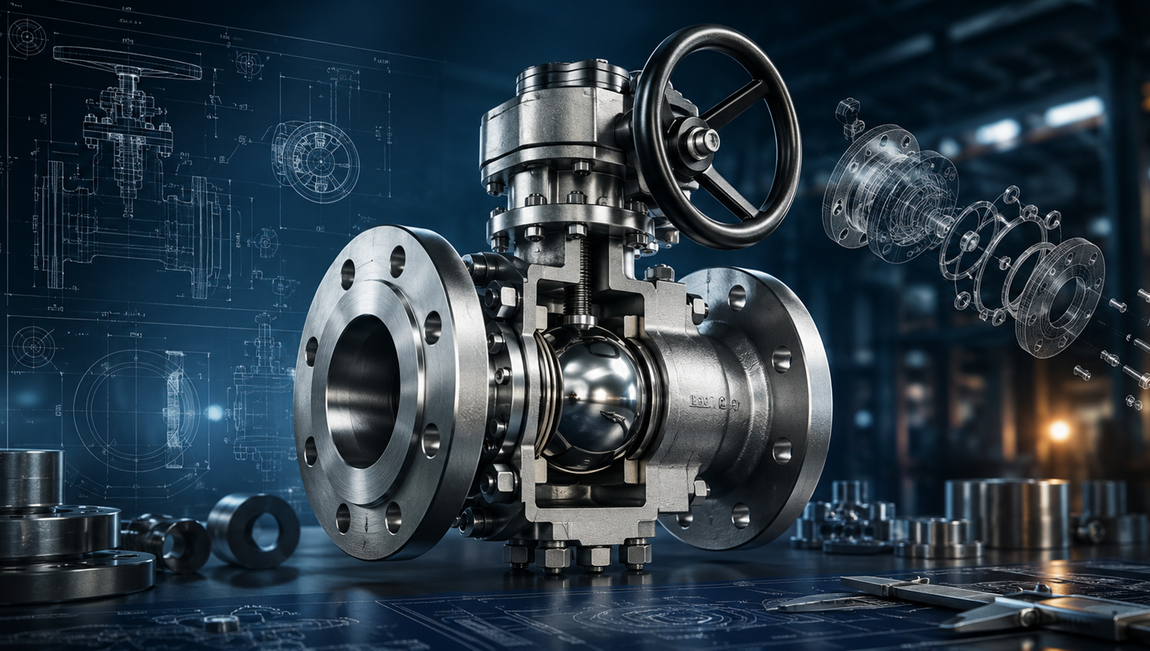
In mission-critical flow control, failure isn't just an inconvenience—it’s a catastrophic event. Whether handling cryogenic liquids at -196°C, managing high-velocity sour gas, or sustaining high-pressure steam cycles, industrial valves are expected to perform flawlessly from day one.
But what separates a standard pipeline valve from a high-performance solution built for harsh conditions? It all comes down to a rigorous, simulation-driven engineering lifecycle.
Here is an inside look at how modern engineering transforms raw requirements into ultra-reliable, field-ready flow control assets.
1. Simulation-Led Design: Overcoming Risk Before the Foundry Pour
Historically, industrial design relied heavily on physical prototyping and generous safety factors, often resulting in heavy, over-engineered, or unexpectedly failing components. Today, advanced Finite Element Analysis (FEA) and Computational Fluid Dynamics (CFD) uncover performance risks long before manufacturing begins.
Using industry-standard platforms like ANSYS, Abaqus, and Fluent/CFX, engineers subject valve designs to rigorous virtual duty cycles:
- Stress & Fatigue Analysis: Optimizing wall thickness and torque requirements while verifying structural integrity under extreme pressure spikes.
- Flow & Cavitation Studies: Mapping the valve's pressure recovery coefficient ($C_L$ or $K_m$) to eliminate high-velocity erosion, reduce noise, and optimize trim geometry.
- Thermal Transients: Ensuring that sudden temperature shifts—especially in severe or cryogenic services—don’t cause binding, differential contraction, or sealing failure.
2. The Comprehensive Engineering Lifecycle
A reliable valve design follows a structured phase gate system. Skipping a single step in this chain compromises predictability, lead times, and field safety.
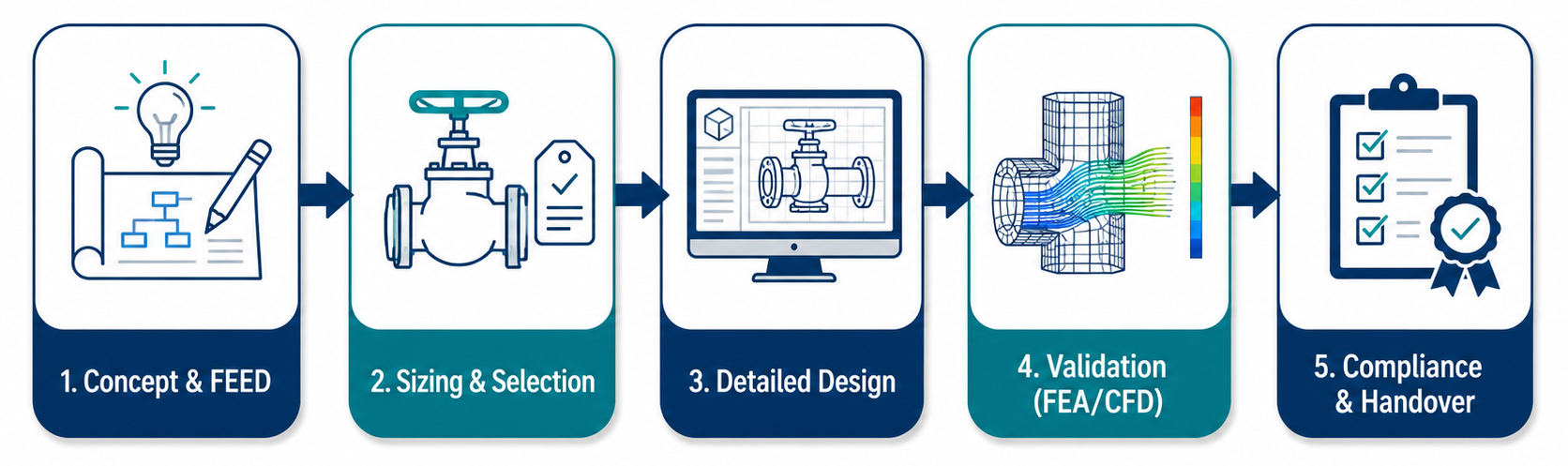
Phase 1: Concept & FEED (Front-End Engineering Design)
Every project kicks off with robust requirement capture. Engineers map out the application envelope, profile critical risks, establish compliance matrices, and align the initial Bill of Materials (BoM) and Material Take-Off (MTO) strategies.
Phase 2: Advanced Valve Sizing & Selection
Flow control is an exact science. Sizing targets focus heavily on calculating the precise flow coefficient ($C_v$) and differential pressure ($\Delta P$). Designers build hydraulic torque curves and map out exact stem, trunnion, and actuator safety factors to ensure tight shutoff under maximum differential isolation.
Phase 3: Detailed Engineering & DfMA
Using 3D CAD modeling combined with Geometric Dimensioning and Tolerancing (GD&T per ASME Y14.5), engineering teams run exhaustive tolerance stack-ups. This stage applies Design for Manufacturing and Assembly (DfMA) principles to balance high structural integrity with cost and weight optimization.
Phase 4: Materials Selection for Severe Environments
Severe service demands specialized metallurgy. Valves must be specified precisely for their chemical and thermal environments, utilizing materials such as:
- Carbon Steel (CS) & Low-Temperature Carbon Steel (LTCS)
- Low Alloy Steel (LAS) & Stainless Steel (SS)
- Duplex & Super Duplex Stainless Steels
- Nickel Alloys (Inconel, Monel, Hastelloy)
- NACE MR0175/ISO 15156 compliant materials for sour gas environments
3. Global Standards and Documented Quality
An uncertified design is a liability. High-performance engineering must natively align with rigid global standards. This ensures total compatibility, pressure-temperature rating compliance, and documented safety during mandatory third-party audits.
| Standard Category | Primary Industry Benchmarks |
|---|---|
| Design & Face-to-Face | API 6D, API 600, API 609, ASME B16.34 |
| Testing & Inspection | API 598, ISO 5208, BS 6364 (Cryogenic Testing) |
| Safety & Emissions | Fire-Safe Design, Fugitive Emissions Type Testing |
Beyond the physical valve, the Digital Documentation Package acts as its twin. Complete traceability requires a transparent Quality Assurance Plan (QAP/ITP), Production Part Approval Process (PPAP) records, material test certificates (MTCs), and detailed General Arrangement (GA) drawings.
Driving Predictability in Your Supply Chain
Unplanned downtime in the oil & gas, petrochemical, or power industries can cost millions per day. Partnering with an engineering team that integrates advanced simulation, deep metallurgy expertise, and strict compliance-driven workflows keeps your project timelines predictable and your operations secure.
Looking for field-proven, custom-engineered flow control solutions built for the world's harshest environments? Explore the advanced technical capabilities and project workflows at the Oswal Valves Design & Engineering Center.